The oil path on the 4.0L is different from the V8s. I'll try to describe it here. The oil pump goes to the filter, which then goes to the lifter gallery. The lifter gallery also feed everything else. From the lifter gallery the oil goes to the main and rod gallery, which the cam bearings intersect. The cam bearings get their oil directly from the same line that feeds the main and rods, so there is no cam bearing gallery of its own. The oil system is different from the various V8s that have a separate feed for the lifters and cam bearings.I6FAN wrote:I6FAN wrote:
Not if it the leak was after the M and R bearings; like the feed line that intersects the main feed and leads to the cam bearings. (How do they drill those anyway, unless they are "cast in"?).
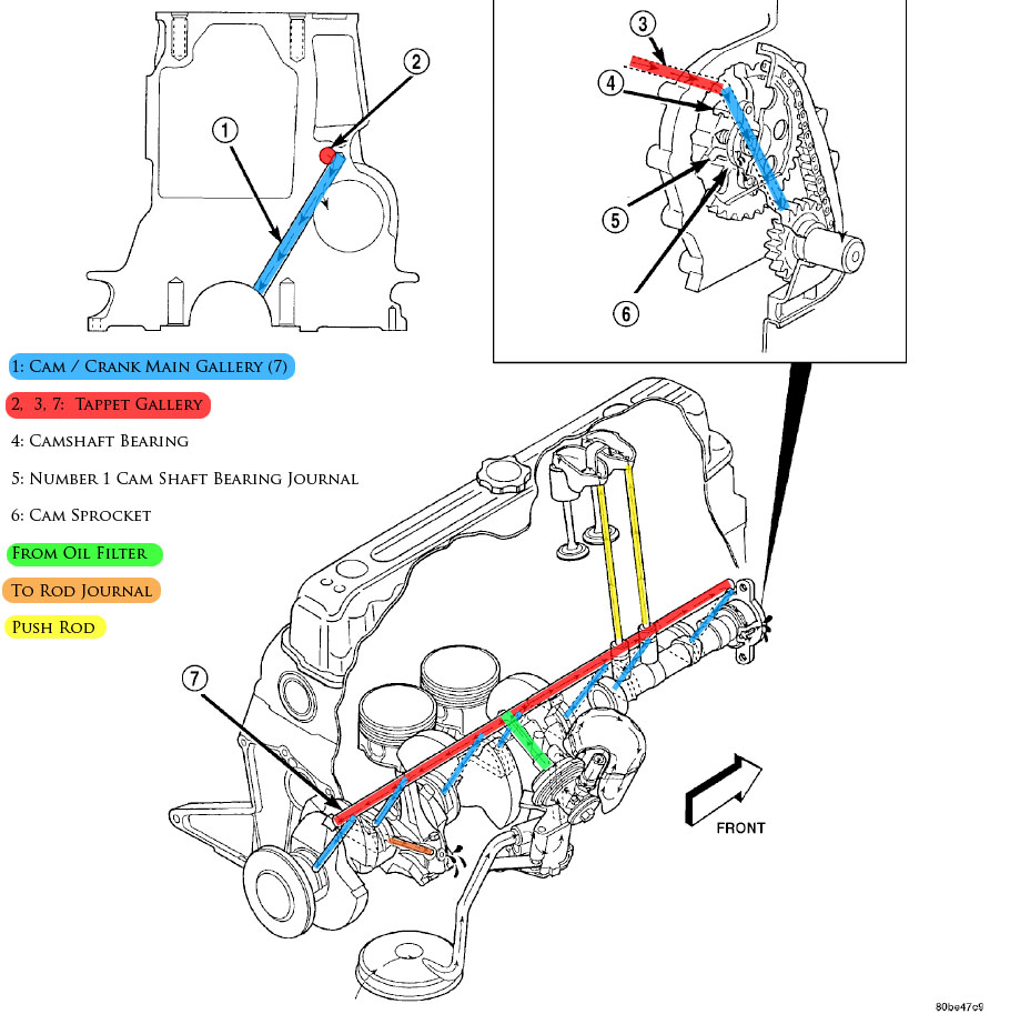
I moved the oil pressure sender from directly off the filter to the end of the block, which is at the end of the lifter gallery, before it goes to the mains, rods, and cam. If there was a leak between the lifter gallery and cam bearings then the main and rod bearings should be showing it as well. And that was at the very end of the gallery, and the #3 cam bearing showed the worse wear all times.Yes it was 40psi, but was it 40psi everywhere it needed to be?
If there is a serious leak it would have to be at the cam bearings themselves.That's right. And these were two big changes that I would think each one, independently, should have yielded results. You would think both remedies together would push you over the top.
But if there is a leak at the cam bearings.... did the leak come first, or did something else cause the bearing wear which in turn caused the leak?